This is the scenario is:
when I disconnect the USB from my laptop and use Bluetooth it goes but this is a very unpredictable scenario & the only prediction is it goes in to the infinite loop is when USB is not connected.
(The processing is very high in the ESP, other than BLE it’s using many protocols like Wifi, I2C, SPI also…)
I guess you are using one of the Espressif chips… there is no USB in any of them (afaik). What is your hardware ? Where are you connected to, how do you see that log ?
My guess is that you have too frequent tasks and are not giving time for completion of the other ones. Check your heap usage, you might be starving it. Disable unnecessary logging, check you are not trashing other tasks’ memory… etc.
I’m using ESP32 chip.
I’ve connected the USB previously… you can see the timestamp and then I was not able to see the Bluetooth, then I connected the USB again so it was showing that kind of Logs…
and previously I was sending data over Bluetooth and was printing that.
There are many tasks running at the same time in the background…
There is no USB on the chip, your device does not know anything about USB being connected or disconnected. In your hardware there is some chip that handles the USB connection and routes data to the UART but the device is always logging (or not).
The only difference on the software side is if you run some program (like mos tool, for instance) that will modify the regular course of actions, otherwise USB connected or not is the same for the ESP32.
Another thing USB-related there is power draining; in addition to my former comments, make sure your device is correctly powered from a stable power source, though that most likely will introduce resets (brown-out, unexplained, etc)
Actually the Power supply is different and the flasher IC is also there for code flashing… but I’m not able to understand why is it going to that mode… because the this conditions occurs only when USB is not connected.
how can I handle Handle Timers in the code? so that 10+ timers won’t disturb any other timer for interrupt. (because I thing it’s a freertos issue…)
I agree with @scaprile, I’ve had issues with power supplies when connecting directly to the device that were not there when it was plugged in with USB.
Most common for me was the power supply not having enough current supply to handle the device during the initial boot when it turns on WiFi and draws the most power.
Double/triple/quadruple check your power setup, or even draw up a connection diagram and share here and someone can comment.
I’ve made a custom board actually… so anyways my power supply is not from the USB… if I need to power my PCB I have to give external power supply with some adaptor or something like that… that’s why I’m very sure that it’s not the power supply issue.
A PS problem will most likely trigger a reset. However, it may wreak havoc in other places.
An incorrectly designed circuit board can cause lots of “unexplained” problems.
On the software side, I don’t understand what you say about timers and interrupts. Are you using hardware timers or software timers ? Software timers are events, there is an event queue and as long as the queue is not full events will be queued and handled one by one in a run-to-completion mode. User code in mOS is like a single task, your code should look like a bunch of handlers with no loops.
Of course the system needs you to let it breath, so don’t use 10ms repeat timers and don’t log every action with long prose.
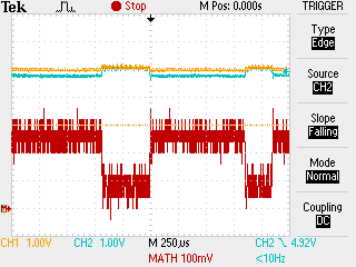
FYI, this is the current profile of an ESP32 with mOS (really old release) starting up and powering WiFi, taken with a .47 ohm series resistor.
Yes Right… I’ve used many software timers and not hardware timers, and handlers also… I’m trying to figure out which interrupt is causing this condition… because in normal flow it’s not giving me any errors…
I got some idea regarding this… like if I can add a handler of core dump for resetting my ESP… please tell me if have any suggestions on that?
If you are using software timers there are no “interrupts”.
If you are using GPIO handlers you also have the option to handle them as interrupt code or event-driven code. In the latter case mOS gets the IRQ and queues an event that will later cause your event handler to be called. All your code runs on the same thread.
You need to profile your code: move GPIOs, log entries and exits, write a code to a bunch of I/Os and watch it on a logic analyzer, etc. The usual tricks of the trade.
You mean how to profile your code ?
You instrument your code… you log when you enter and when you exit tasks… LOG(LL_DEBUG, ("task: %u", state)); ... LOG(LL_DEBUG, ("task exit: %u", state));
Since printf can affect your timing, when dealing when too short or too frequent tasks (or irq handlers) you can move a GPIO, lets say set on entry reset on exit, then you connect an oscilloscope, see that pin, and you know how frequently you execute that task and how long it takes to run. Two tasks, two pins, and you can also see if one preempts/interrupts the other (which won’t happen if you use soft timers and handlers on mOS).
A more advanced trick is to write a code telling where you are and what you are doing to a group of GPIOs, then you collect them with a logic analyzer and you have a detailed trace. Let’s say you take the four LSB on port A, then you have 16 possible codes, you assign 0 for idle in main loop, 1 for entry task A, 2 for exit task A… and so on. Connect the 4 pins to 4 inputs in the LA, define them as a 4-bit bus set the LA to show bus data, and enjoy debugging.
I guess It was a problem with the power only… I tried a dedicated power supply to esp32… it solved my problem.
I found another way to solve this problem… we can go with the capacitors to solve the problem. we just need to find out the perfect value of Capacitor…
The bulk capacitor just needs to hold enough charge to fill the surge for the load until the rest of the power supply can replenish it.
Sometimes people forget the proper name for those wires inside the USB cable is “inductor + resistor”.